You are currently not logged in.  Logon or register to access more features. Vision-Riders.com is a FREE service provided by Victory Riders Network.
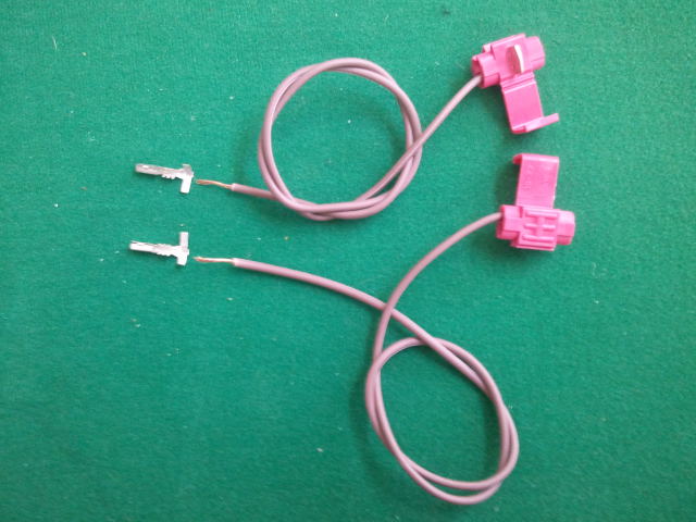
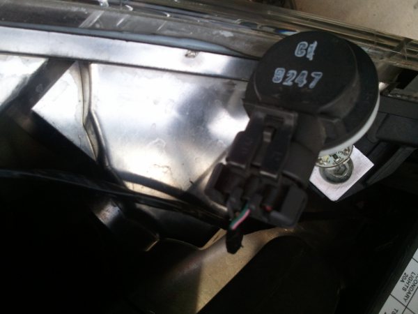
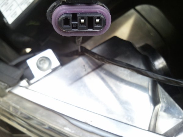
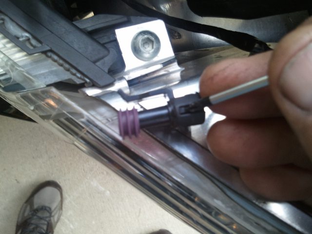
Search:


FRONT TURN SIGNAL INNER BULB MOD.
Jump to page : 1
Now viewing page 1 [25 messages per page]
View previous thread :: View next thread
   Discussion -> Vision Tech ReferenceMessage format
 
Nozzledog
Posted 2012-10-29 5:44 PM (#125877)
Subject: FRONT TURN SIGNAL INNER BULB MOD.


Visionary

Posts: 1228
Rancho Cucamonga, CA
FRONT TURN SIGNAL INNER BULB MOD.

The inner bulb mod allows all four bulbs to act as turn signals instead of just the outer two.

Difficulty Level : 1

Cost : $1 - $4

Items needed:

2 - Terminal connectors : CONN-56256 GM Delphi / Packard - Sealed Metri-Pack 150 ( Metripack ) Female Terminal ( 20 - 16 gauge ). They can be bought from Ballenger Motorsports. http://www.bmotorsports.com/shop/product_info.php/products_id/484
2 - 10" - 18g wires
2 - Wire taps


Tools needed:
Small screwdriver (jewlers)
Pliers or crimping tool
Paper Clip
Drill and bit (to drill holes in plugs - or just buy grommets)

Procedure: Start with bike OFF.

1. Remove front fairing access panel.
2. Remove Left and Right inner bulbs from cradles (lens).
3. Unplug Left and Right inner bulb harnesses at the bulb connector.

You will notice that there are only two pins inside the connector. We are going to add the third.


4. Remove the wire lock on the back of the harness connector (This is what keeps the wires in place. You may need a small screwdriver to help pry the tabs loose).


5. Use a small screwdriver or paperclip to push the red plug out of the wire housing.

Snap off the ends of this plug and drill a hole thru it for the piggyback wire to go thru (you can by a small grommet if you would rather)

6. Assemble the 2 sets of four pieces from 'Items Needed' to make the two piggyback wires and push the wire plug/grommet over the wire by the terminal side


7. Push connector pin into back of empty slot, making sure direction matches the other two.

8. Reconnect back wire lock

9. Connect the wire splice end to colored outside wire (not the black one) on the outer bulb harness. In this picture, it is the white wire connecting to the blue wire (the other two taps are for a load equalizer)


10. Reconnect harness to bulb and check to see if blinkers work properly ( turn bike on, test blinkers)

11. Re-install inner cradle with lights into lenses.

11. Replace Font Access Panel

12. Post pictures/video of a job well done on Vision-Riders.com


Pictured with LED Mod also

Edited by Nozzledog 2012-10-29 7:37 PM
Top of the page Bottom of the page
Jump to page : 1
Now viewing page 1 [25 messages per page]
Jump to forum :
Search this forum
Printer friendly version
E-mail a link to this thread

Copyright © 2007-2024 Victory Riders Network™